The Menu Bar accesses a host of functions including simulation options and settings, and viewing options and settings. Many of the main menu bar function are duplicated in the toolbar buttons.
Fig. 2.1.1: The Menu Bar.
"File" Menu
New/Close - Erases the model currently in memory. An option is given to save any unsaved changes from the current model. The previously used Level, Layer and Pump Database will be retained for the new model. The New option closes the model, and load up the system startup defaults, whereas the Close option closes the model, but retains the previous model settings and defaults.
Open - Loads a pre-saved model. You can also open Pumpsim™ files by dragging file icons from your Windows folders onto the Pumpsim™ screen.
Merge - Joins two models together instead of erasing the currently loaded model. Similar to the Open command, this may be useful for joining separate modelled areas of the same site. Caution should be taken however, as duplicate objects are not immediately checked when the models are merged (duplicate objects will be subsequently be deleted if an attempt is made to simulate the model).
Save - Saves changes made to the model. If the Pumpsim™ title bar shows that the model is untitled, the user will be prompted to select a name before the file can be saved.
Save As - Saves the model, but gives the option of saving under a different name. Pumpsim™ can be saved in one of two formats. The default format in the PSM file, which is the standard file format. This format is highly compressed and cannot be read by other programs.
Pumpsim™ files can also be saved as a Text format. This format follows the standard TAB separated values format and can be loaded by programs such as Microsoft EXCEL, WORD or ACCESS. The internal contents of the file can be viewed, modified and resaved as a Text file. The Text file can be reloaded into Pumpsim™ providing the basic structure and the HEADER and FOOTER tabs remain the same.
Master Link
Fig. 2.1.2: The Master File window.
Enables a common settings file (Master File) to be linked and shared with multiple Pumpsim™ files.
Master Files store a user definable selection of shared settings (for example resistance and friction factor preset values or pumps). When a Pumpsim™ file is linked to a Master File, and the file is saved, the settings are also saved to the Master File and will be available to all other Pumpsim™ files which have a link to the Master File. The settings in linked Pumpsim™ files are updated from the Master File when loaded. If the Master File is not available, then a warning will show and the most previously saved settings will the used.
Warning: Using linked Master Files can be dangerous if settings made in one file adversely affect another linked file. For example if a pump is removed or replaced with another pump, and the file saved, then all other linked Pumpsim™ files which used to use this pump may no longer work correctly. If a linked Master File is used, it is normally better to add new settings, not remove or delete existing settings which may be used by other files.
Create New - Creates a new Master File template, which can then be linked to other Pumpsim™ files. When creating the file, it is automatically linked to the current file. Other Pumpsim™ files can be linked to this same Master File by opening the files and using the Link option below. Save the Master File in an accessible file location. A descriptor can be saved with the file to explain information about what components have been saved.
Hint: When creating a new file, there is an option to specify what common settings you would like to make in the master file. For example if only the pump database, and the common resistance, friction and shock factors are to be used, then click on the Pump Database, and Preset options in the dialog box.
Link - Opens a dialog form to search and link to a Master File. If the current Pumpsim™ file has an existing linked Master file, the new Link will replace the data in the Pumpsim™ file. An alternative method to link a file is to simply drag and drop a Master File into the current Pumpsim™ window.
Unlink - Breaks a link to the Master file (but does not change the Master File). Any changes to file settings made after the link is removed will no longer update the Master File.
Update - Refreshes the current Pumpsim™ file with the data in the Master file. This may be necessary if another file has modified the data in the Master file after the Pumpsim™ file has been opened. It is normally not recommended to have multiple files open accessing the same Master File as only the most recently saved Pumpsim™ file will have updated the master settings. If another file has updated the Master File while the current file is open, then a WARNING will display indicating a possible conflict.
Caution: When selecting ‘REPLACE’ many components such as pumps databases, levels and most presets may not correctly map to the existing model’s pumps, levels and presets, particularly if (for example) pumps within the database are in a different order. These may need to be manually corrected by checking and re-editing pump pipes to ensure the correct pumps have been placed.
Defaults (Pumpsim™ Startup Settings)
The Defaults file is stored in the user’s personal Windows directory. The file is loaded when Pumpsim™ starts and specifies the settings, behaviour and pumps when the program is first loaded. Each user who logs on to the computer will have a different default file which is initially created when the program is installed.
Pumpsim™ files have a copy of defaults stored within the file which may have been modified after the model file was started. This will override the standard start up defaults when the file is loaded.
Save
Saves the settings currently loaded in memory to the defaults file. These will be loaded automatically next time the program is run.
Restore
Restores the defaults file to the original file created when the Pumpsim™ program was installed.
Refresh
Reloads the original defaults file that is first loaded when Pumpsim™ is initiated.
This may be required if the default settings that are automatically loaded with a Pumpsim™ simulation file are incorrect or out of date, or you wish to overwrite the current file settings.
Caution: This will reset all file parameters such as pumps databases and graphics options. If you wish to only update selected components, use the inherit function to load selected components from an existing file.
Inherit Attributes
Adopts selected attributes from another model. Pumpsim™ files contain many different components such as pump databases, file and simulation settings, level and layer database and many other options. Instead of setting up new parameters for a model, these components can be loaded from an existing file without deleting the pipe data in the current file.
Fig. 2.1.2: The inherit attributes menu. Parameters of a model may be added to a
Pumpsim™ model.
Hint: Pumps from other Pumpsim™ files can be used in your existing files by inheriting and ‘combining’ the pump databases. The simulation file pumps inherited will only be added if no existing pumps exist with the same name. The ‘merge’ option will ensure all the current model pumps will be preserved, and new pumps made available for selection. The pump list can be edited from the pump database, or from the Presets spreadsheet.
Once a suitable file is selected, an option panel is displayed to allow the user to select various components they wish to inherit from the saved file. Once loaded, these components will become part of the existing file. An option is provided to merge presets with existing presets (for example, the friction factors may be added to a list of currently used friction factors), or completely replace existing presets.
File Tools
A series of tools to assist with securing, comparing or linking pictures to Pumpsim™ files. The tools are described below.
- Compare – Compares the current loaded file with a saved file. Any obvious changes to pipes such as moving, deletion, new attributes, presets or sizes will be highlighted on screen and in the error list box.
Hint: This function may be useful where there may be multiple similar versions of the same file, and it is unknown what changes may have been made between versions.
- Security – Sets the file security with a password to prevent unauthorised changes or access. In addition, a password protected file cannot be merged with another. To activate security for a file, simply select this option, enter a password and click what security option you wish to apply.
- View Only – Allows the model to be loaded and viewed, but not changed in any way or re-saved.
- Read Only – Allows the model to be loaded and modified, but not resaved or copied to a new model.
- Lock File – Prevents the file from being opened or viewed.
When a security enabled file is loaded, Pumpsim™ will request a password. If the password is not entered or is incorrect, only the restricted security access option will be available.
Caution: Passwords are case sensitive. Ensure you can recall the password. A lost password means the file will not be able to be opened or changed in the future.
Import
Imports external data into Pumpsim™ to build model. Pumpsim™ can import data from TXT (text) files, DXF (drawing exchange format Autocad) files, DWG (Autocad native format), STR (Surpac string files), DM (Datamine Files – String or Wireframe Solid) and VDP (VnetPC™ files).
Export
Provides a utility to export Pumpsim™ centrelines, text and solid graphics to a DXF file for importing into other CAD software. The colours and text exported will be set to the current screen colours and text. Different items can be selected for exporting. They will be placed on different DXF layers so they can be turned on or off independently in the CAD program.
Note that any pipeline attributes will be lost during the export process, and DXF files cannot be re-imported back in to Pumpsim™ as pumping network models.
Manage References
Provides a utility to separately manage any imported graphics reference. Each imported object can be separately coloured, made transparent or hidden from the main view through the form options.
Fig. 2.1.3: The referenced graphics menu. Allows the user to
reference different imported elements of a model.
Select one or more graphics objects from the list with the mouse (hold the SHIFT key down to select multiple items). A [+] against the name indicates it is currently being shown. A [-] indicates it is currently hidden.
- Colour – Changes the colour of the items. The second colour shows the transparency effect on the colour. Clicking the multi-coloured box will colour the reference graphics object with a full spectrum of colours based on elevation.
- Transparency – Changes the transparency of the item.
- Memory – Shows the current internal Pumpsim™ memory reserved for storing reference graphics. If this approaches 100%, consider removing some reference graphics objects, or alternatively if the computer has sufficient memory increase the Reference Graphics memory from the Settings > Settings menu.
Right click on a reference to open other options:
- Hide – Hides the object from the screen view
- Show – Shows the object in the screen view
- Merge – Joins together two or more selected files from the reference graphic list.
- Delete – Removes the reference object from the file
- Remove Duplicates – Search all reference graphics for duplicate graphics and removes any duplicates to reduce memory requirements. This function does not remove duplicates on different reference layers.
Title Note
Allows the user to specify a unique file comment which appears in the top title bar. This comment can help identify the date, name and purpose of the model.
File Memo
Allows users to write an extensive descriptor regarding the function or description of the current model. This is saved with the file for future reference.
Print Image/Print Vector
Prints a graphic picture of the model in the View Window to an installed printer.
Only printers with Windows supported graphics capabilities will be capable of printing the model. As Pumpsim™ uses a perspective view, no particular scale is applied to the image. The image is sized to the maximum size of the page and orientation. To reduce colour output, the Pumpsim™ screen colours can be changed under the Settings > Settings > Graphics > Colours menu. For detailed engineering accuracy output, it is recommended to export the model to a DXF file for loading into a suitable CAD program for later output to a printer.
Load Demonstration
Pumpsim™ comes pre-loaded with some generic models of typical mines. These models is for demonstration purposes only, and contains a number of simple site examples to view. Note that while these items can be modified, they cannot be resaved in the same folder.
Licence Manager
Opens the License Manager form.
Exit
This command closes Pumpsim™. Pumpsim™ will prompt if your model file, pump database or defaults have not been saved since last modified.
Undo
Reverses the previous action. Undo is a fully functional undo facility that will undo a number of previous changes made to a model (up to the buffer size of the undo function). Note that while it will not directly undo a simulation, by pressing UNDO until your previously model is in place and then re-simulating, this will produce the same results.
Redo
Redo will reverse the result of the undo function.
Copy and Paste
- Copy pipes from one Pumpsim™ program to another.
- Copy and Paste objects creates an exact replica of selected existing objects in a model and pastes them into the same location into the existing or new model. The function is primarily designed to copy and paste pipes between Pumpsim™ files or between different stages in a pumping network design; for example to update pipes from a model that has been modified.
- To use this function to copy and paste between models, ideally have two copies of Pumpsim™ open with different model files. Select the Copy menu item, and click on, or fence the pipes you wish to copy.
- To paste the pipes, move to the new model (or load it up) and select the Paste TRUE menu item. The copied pipes will be pasted into the new model at the same coordinates as the original pipes.
- To paste duplicate objects between Stages, use the same technique, but simply copy the object in one stage, switch to the desired stage name or number, then Paste pipes TRUE. A copy of the pipes will be set in the new stage.
- If pipes become duplicated in the process, Pumpsim™ will delete one of the duplicate copies.
- To paste objects in a different location, use the Paste pipes LOCAL menu option. This will paste the pipes around the current local screen location set in the view window, effectively copying the pipes from the original location to a new location.
Clone and Apply Attributes
Fig. 2.1.4: The Clone options window.
Attributes are physical pipe parameters such as size, friction factors and shock losses, as well as identifying attributes such as layers. You can decide which attributes to apply to an existing pipe by selecting the Clone Options function from the menu or Select Manager Form from the toolbar.
To clone attributes, select the Clone Attribute menu item, and click on an existing pipe. The pipe properties will be copied to memory and the program will automatically enter the Apply Attribute mode.
To apply attributes, make sure you are in the Apply Attribute mode if it has not already been selected and either click on an existing pipe, OR fence a selection of pipes to apply the attributes to that group. Cloned Attributes can be applied at anytime (even after other editing has been done) and will apply the most recently cloned values.
Example: An existing pipe has been set as an exhaust pipe with custom primary and secondary layers. To copy these attributes on to other pipes,
- Select Primary, Secondary and Fluid Type options on the Select Box
- Select Edit > Copy Attributes
- Click the pipe you wish to copy the attributes from.
- Select Edit > Paste Attributes
- Click or Fence the pipes you wish to copy the attributes to.
New Pipes
Control which attributes are applied to new pipes.
- Use Inherited – New pipes drawn from existing pipes will inherit the settings from the pipes they are attached to (such as size, shape, friction factors etc). pipes which do not originate from another pipe will use the default setting values.
- Use Defaults – To force the program to use the Default Values (from the Settings Menu), choose Default. All new pipes drawn (regardless of whether they connect from existing pipes) will use the default settings.
- Use Cloned – Forces the program to use the Cloned Settings from a previously cloned pipe. For example if a pipe is to be drawn from a horizontal pipe, cloning a similar pipe and then drawing the new pipe with this function set, will result in a new shaft with the same size, parameters and layer settings as the cloned pipe.
Find / Find Next / Find ALL
Automatically locates specific pipes and moves the screen to selected parts of a model.
Fig. 2.1.5: The find command, as accessed through the edit tab.
Selecting one of the options will find and highlight the object searched for. The option may be repeated for further objects by pressing the Find Next menu function, the Find tool bar button or by pressing <F3> on the keyboard.
Hint: Pressing <F3> will rapidly allow you to search through a model, by repeatedly jumping to the next item. To view more detail about the items being jumped to, leave the EDIT BOX open. The EDIT BOX will instantly update with detail about every pipe that is jumped to.
Highlight or Select All
Highlights or selects all objects matching the previous find criteria. To find all instances of an object (for example to find all objects with the name ‘shaft’ in the pipe name, or to find all pumps, click on an initial find type and then click on Find All. All items with these parameters will highlight and flash.
For example, if FIND was used to locate an object with the name “M52 Decline”, Select All would select ALL objects with this name in the pipe name field. The selected pipes could then be edited or manipulated as a group.
Fit All
Fits all the display data into the view window.
CAUTION: If display data is from two regions a long way apart (for example data may have been imported into Pumpsim™ from a different coordinate system). Fit All may not be able to accommodate the range of data attempted to be shown, or the camera may be too far away to view the data effectively. Ensure all data is in the same coordinate region before it is loaded or merged.
Show All
Resets all hidden levels, layers and data and displays the entire model. Occasionally a model may have hidden or semi-transparent pipes set from a previous action. Show All will quickly bring the entire model back to full view. Show All will force Pumpsim™ to show all elevations of data in your model, even if they are outside of the ranges specified in the Level Database.
Reset Display
Resets the graphics display adaptor and re-establishes the graphics on the screen. Some types of hardware graphics display adaptors may occasionally corrupt or fail to show the screen graphics, particularly if the computer has been brought out of hibernation, sleep or screen saver. This option in most cases should recover the graphics.
Quick View
Quick Views can quickly be saved and recalled sequentially outside of the normal Saved View system. Quick Views are not added to the Save View menu selection. The views can be quickly recalled at any time using the arrow keys. The function primarily assists with navigation of large models, where different areas can be quickly returned to for viewing simulation results.
- Save Quick View – Creates a temporary view position for a model. The view is added sequentially to previous stored Quick Views. The sequence of stored quick view can be recalled or returned to using the LEFT and RIGHT arrow keys.
- Clear Current – Clears and removed the currently recalled quick view. The view is removed from the sequence of other stored Quick Views, and can no longer be recalled.
- Clear ALL – Clears all Quick Views from memory.
- Previous Quick View – Recall the previous Quick View from the sequence of saved Quick Views.
- Next Quick View – Recalls the next Quick View in the sequence of saved Quick Views.
Copy to Clipboard
Copies the screen to the Windows clipboard for direct pasting into an external documents (such as a PowerPoint presentation). Static Views are primarily for referencing areas before and after simulation.
Copy to Clipboard (all)
Similar to above, but copies any overlying windows (such as legends and graphs).
Copy HI-RES
Similar to above, but copies an ultra-high resolution picture to the clipboard. This picture has more detail than the screen graphics, but may fail to work on slower or older computers. Hi-Res pictures will show more clearly in large format printing or reports, but are of less use in screen or projector presentations where the screen cannot show the higher resolutions.
Snapshot
Creates a picture copy of the current window in a new form window. Static Views are primarily for referencing areas before and after simulation. It may be useful in showing a sequence of changing pumping simulation results by storing previous results for comparison with new results.
The form window defaults to 25% of the size of the normal view window, but can be resized or maximised at any time to show full detail. The static view forms can be renamed for reference or saved to a picture JPG file for future use in other software.
Static views are simply picture copies of the original model graphics and remain the same regardless what happens to a model after the static view is created. They cannot be edited, moved or rotated. The number of static views created is only limited by the memory capacity of the computer.
Hint: Both the EDIT box and the pump DATABASE form can also be reproduced as a STATIC view. This is useful to provide a quick comparison between pipes or model results before and after simulation changes. To use this function, simply RIGHT click the EDIT box or pump form, and select Static View.
Set Edit Centre
Sets the edit grid and point of focus to a specified coordinate or elevation. New pipes will be drawn on the specified elevation.
Show All Elevations
Shows all elevation ranges for the model. Turns on all level elevations views, and includes pipes and references outside of the defined elevation ranges.
Show All Layers
Shows all layers (primary and secondary) in the model. Turns on all layers so all pipe graphics will be visible.
Hide Zero Flow
Hides pipes with no flow. This function is useful for hiding disused or non-flowing parts of a site so they do not clutter the display. Pipes with no flow (or flow below the level set as zero flow value in the Settings menu) will be shown as transparent or hidden, depending on the transparency settings described above, and the transparency amount set in the Display Manager.
Hide Excluded
Hides pipes which have been set as EXCLUDED from the model. This function is useful for hiding parts of a site which are not required to be simulated, or are not set to be part of the current simulation model. The exclude options for pipes are available from the EDIT box.
Hint: An old sealed off development, or a future development yet to be mined can be excluded from the model to speed up simulation and display of models. Excluded pipe can be hidden to simplify the display, but can be shown and converted back to normal pipes at any time if required.
Save New
Saves the current view and stores the save name in menu for future recall. Save view will save all attributes in a view including RL levels, layers and display options. Saved views can be pulled back into any current window by selecting the saved name from the pull down view list.
Delete View
Deletes the saved view stored in the CURRENT pull down menu list (and hence removes this name from the list).
Saved Views
Four view orientations are set as defaults:
- PLAN
- EW SECTION
- NS SECTION
- ISO
These standard views will display the model at various orientations, although the model can still be orientated to the same orientations by using the RIGHT mouse button. These views cannot be deleted or changed.
Caution: The Perspective view will distort some aspect of the views. For example, the plan view will show the pipes at the EDIT grid level to plan, but pipes above and below this elevation will appear larger and smaller respectively.
Any further saved views will be placed below these items. Saved Views save the position, orientation, colour scheme, data types and attributes of the screen at the time at which they were saved.
Hint: Saved views are not only useful for recalling the location and orientation of a model. Because they recall selected levels, layers, data types and colours, they can be a quick way to establish a template to edit and view different data aspects of your model. For example, you may have an FLOW view, custom set to highlight a certain range of flows in different colours, while a ‘HEAT’ view may be saved to highlight a range of temperatures.
"Run" Menu
Flows
Undertakes a steady state uncompressible flow simulation of the model.
Summary
Displays a summary of the current model collectively, or grouped under different tabs. The data may be copied to the clipboard, for pasting into another package such as Microsoft Word, or an email.
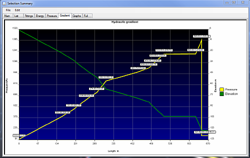
Fig. 2.1.6: The Gradient tab of a Selection Summary window.
- Main – General information about the model
- List – List of all elements in the model.
- Cost – Calculate the cost of installation and power in the selected part.
- Fittings – Information about pumps, valves and other fittings
- Energy – Energy summary
- Pressure – Pressure summary
- Gradient – Only available if a line is selected. Shows the hydraulic gradient. The higher point will be on the left.
- Graphs – Energy loss graphics
Fig. 2.1.7: The graphs tab demonstrating energy loss graphics of a network summary.
A selection of tools and settings to check, modify and fine tune the model.
Pumps
Displays a windows form that allows editing, adding and deleting of all pumps in the model pump database. Up to one thousand (1000) pumps and the associated pump curves may be entered into the pump database. A display for each pump curve and data will be presented when a pump is selected from the display list.
For further information on entering and using pumps, see the pump section in this manual.
Levels
- A list of elevation ranges on which pipe data can be individually viewed.
- This form allows editing or creating of a list of levels (elevations) between which pipe data is located. The level list can contain up to 1000 levels on which your model will be created.
- Elevation data can be edited in any order, as well as added at a later date - Pumpsim™ will sort the data from highest to lowest when next displayed.
- To select which levels are displayed, use the Data Display manager to select what levels to display. Alternatively, levels can also be independently set by using the mouse context pop-up menu (right mouse button on the screen) to Select Levels.
- To view ALL levels at any time, simply use the Right Click pop-up menu to select All Levels. Levels can be sorted by clicking the column header for the desired item.
Spreadsheet
- Displays a READ-ONLY list of currently viewed or selected pipes in a spreadsheet form.
- The spreadsheet of pipe data displayed can be copied and pasted to other applications such as Microsoft Excel or Word.
- Up to 100 different types of data can be displayed on the spreadsheet. To display different data types, use the SELECT > DATA OPTIONS menu to select the data you wish to display.
- Data can also be removed from the spreadsheet, by selecting EDIT > REMOVE or using the right mouse button.
- Data columns can be reordered by selecting the column title and dragging to a new location. In addition columns can be resized and resorted by using the appropriate menu commands.
Hint: While the spreadsheet function is not designed for editing data, extensive data characteristics for each pipe can be displayed, and copied to external programs such as Microsoft Excel™. Pumpsim™ provides an Index number and a Unique number reference for each pipe. The Index number is referenced internally and during simulations by Pumpsim™, but may changed for each pipe as pipes are added or removed. The Unique number will not change, and should be used as a permanent reference number to each pipe if other identifiers such as names are not used.
Filtering Tools
Filtering Tools consist of a selection of pipe utilities to help filter and correct complex, disconnected or overlapping raw model data. The tools can be run simultaneously as a group, or individually.
Fig. 2.1.8: The Filter window, used to filter and correct raw model data of pipes.
The "All Tools" tab in the form, allows simultaneous filtering using the various selected tools. Alternatively, each tool can be selected and run individually from the other tabs.
Simplify
Simplify allows the user to reduce the number of pipes in a model to a more efficient number without affecting the overall model analysis.
It is particularly useful where a model has been imported via a DXF file and contains a large number of very detailed but unnecessary small connected pipes.
Simplify will search a model for sequences of pipes that may be reduced to single straight pipes. In doing so, much of the overhead and effort required to set parameters to every pipe can be reduced. Note that the simplify function will only combine pipes that have a single entry and exit. Pipes at junctions and split objects will remain untouched.
- Maximum Joined Angle – The Maximum Joined Angle option specifies the maximum angle between two pipes being considered for merging. For example, if the original model contains a number of pipes that form a curve and Maximum Joined Angle is set to 20º, Simplify will keep on merging pipes until the pipes being considered have directions changed by 20º or more.
- Maximum Joined Length – The Maximum Joined Length option restricts simplification to pipes less than the specified length. For example if set to 30m, only pipes with lengths of less than 30m will be considered for merging and simplifying.
- Use combined lengths – Ensure the new length of a combined pipe is fixed to remain exactly the same as the original combined lengths even if the original pipes formed a curve. If not set, the new lengths will be recalculated as the true length of the new straight line. In most cases the difference is minor, and it is recommended to leave this option unchecked.
- Ensure no resistance presets filtered – Ensures that pipes with a preset resistance (such as a block pipe) are not simplified and merged with other pipes.
- Ensure pipes dimensions are the same – Check to see if pipes that are considered for merging and simplifying are only joined if they are exactly the same size.
- Ensure wall types are the same – Similar to dimensions, only pipes with similar wall (friction factor) types are joined.
- Selected pipes only – Only simplify selected pipes and ignore all others.
Note: In general, the higher the values of the Maximum Joined Angle and Maximum Joined Length settings, the more aggressively Pumpsim™ will simplify and combine pipes.
Hint: Short irregular pipe segments are best simplified with high joined angle settings (+45 degrees) or smaller joined length settings (<20m). Long smooth pipe segments are best simplified with low joined angle settings (<20 degrees) and high joined length settings (>50m). Note that pipes can be individually selected for simplification.
Binding
Fig. 2.1.9: The Binding tab of the Filter window.
Binding connects disconnected pipes ends or intersections. Many imported DXF files do not have correctly connected centre lines or ends. This function will search for unconnected ends or crossed pipes and join them together if they are close enough. Pipes must always be correctly joined to allow flow.
Warning: These functions are intended for preliminary clean-up of new models, not for existing balanced models. It can permanently change the characteristics of your model and may delete some preset items or values. Ensure only the required pipes are first SELECTED before binding or simplification.
- Bind loose pipe ends – Defines the distance to join pipe ends in a model which are close together but do not join. Imported DXF file commonly have lines which don’t exactly join due to editing or drawing methods used in the original file. Pipes which do not exactly join in Pumpsim™ will not flow, and will result in a No Exit / Entry warning. The search radius can be entered in the preset box. For example a search radius of 4 will join any loose end (pipe end without another connection) to any pipes within 4m of the end.
- Bind adjacent nodes – Defines the distance to join adjacent connected nodes in a model which are close together but do not join. This function is a little like simplify, in that small pipes between the joined nodes will be removed.
Warning: Selecting this option with too greater distance can seriously distort the model. Use with caution or not at all.
- Bind pipe ends to Junction – Defines the distance to join pipe ends to other pipe mid sections. It effectively splits and joins into the new pipe. Imported DXF files commonly have lines which cross the path of pipe ends, but do not have a joining node. This function will create a joining node along the line.
- Bind Permanent Node – Defines the distance for joining fitting. It effectively splits and joins into the new pipe. This function will create a joining node along the line.
- Bind Crossed pipes at Intersection – Defines the distance for joining pipes that intersect or come close to intersecting, but do not have a joining node. It effectively splits and joins both pipes into new pipes. Imported DXF file commonly have lines which cross the path of another pipe, but do not have a joining node.
- Duplicates – Searches for pipes which have duplicates in the same or similar position. Duplicate pipes can cause problems with simulation due to poorly defined or hidden flow paths that the user cannot see.
Fig. 2.1.10: The Duplicates tab of the Filter window.
- Adjacent Angle is the maximum angle difference between adjacent pipes that may be considered as a duplicate. Pipes next to each other with greater angles between them will not be considered as a duplicate. The smaller the angle in degrees, the more ‘parallel’ and pipe must be to be considered a duplicate.
- Adjacent Distance is the maximum distance two adjacent pipes can be apart over which they will no longer be considered as duplicates.
- Exact selects only an exact matching pipe as a duplicate
- Reversed selects pipe the same, but facing opposite directions.
- Similar selects pipes that are similar but not identical. The adjacent angle and distance will be used as a criterion for selection.
- Action defines what action will be taken when the duplicate pipes are found.
Convert To 3D
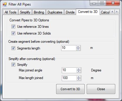
Fig. 2.1.11: The Convert to 3D tab of the Filter window.
Moves the model pipes on to a 3D surface or contour plan, effectively converting the model from a 2D plan to a 3D model. Note that if only parts of a model need to be converted, they should first be selected with the Select tool.
- Use Reference 3D Lines – Uses lines (such as contours) loaded in from a DXF as a reference to convert the model to 3D.
- Use Reference 3D Solids – Uses solids (such a terrain polygons) loaded in as a referenced DXF object, to convert the pipes to 3D,
- Create segment – Break the pipes in small section in order to obtain a better adjustment.
- Simplify – Join the pipe together after adjustment in order to decrease the number of pipe.
Hint: To convert a multi-seam or level model to 3D using this function, individually group-select the pipes required, and ensure only the relevant 3D DXF object for that level is turned on before conversion.
Utilities
The Utilities sub menu provides many functions to assist with the manipulation of pipe data, particularly raw data which may have been imported from a DXF file or similar.
Swap Axis
Swaps the Easting and Northing (X and Y) coordinates of all pipes in the model. This may be useful where the coordinate system in Pumpsim™ does not match the directions used on the Site Plan Grid. Where the direction of the coordinates needs to be reversed, use the Settings > COORDINATES settings to change the direction of the axis coordinates.
Rotate Coordinates
A utility which rotates all (if none are selected) or just the selected pipes by a number of degree around the point of focus. The point of focus is always at the centre of the screen. It can be set by middle clicking the mouse button on a point, or by entering the centre coordinates in the View > Set Edit Centre option.
Reverse Coordinates
Changes the sign of pipe coordinates from positive to negative or visa-versa. Not that this is similar to mirroring coordinates around a zero centre.
Scale Coordinates
A utility which scales all pipe or reference coordinates by an input factor. This effectively reduces or increases the size of the model without changing the pipe size. A pipe length will not be changed if it has been fixed.
Warning: This function should only be used to scale schematic pumping model with predefined fixed pipe lengths. Scaling a model without fixed length will change the pipe length and resistance, making it invalid for true scale model simulation.
Scale Pipe Size
A utility which scales all pipe dimensions by an input factor. This effectively reduces or increases the size of the pipes in the model.
Hint: This function will recalculate pipes lengths and hence change any previously fixed lengths. If there are any doubts, use the EDIT function to individually fix/unfix lengths of only the pipes that need to be changed.
Pipes
Auto Name
Automatically places a code number on every pipe without a current pipe name. A letter may be specified to head the number if desired (e.g. B157).
Resequence Index/Unique Numbers
Sequences the order of pipe numbers in a Pumpsim™ model.
- Index numbers are dynamic numbers representing pipes stored internally in Pumpsim™. The numbers may change as pipes are deleted or added. Pumpsim™ uses index numbers to refer to pipes during simulation and when identifying problems. All index numbers are sequential and the highest index number will be the sum of all pipes. Resequencing index numbers renumbers all pipes from higher elevation to lowest elevation, easting to northing.
- Unique numbers are static numbers which do not change when pipes are deleted or added. Numbers are sequenced incrementally from the last highest unique number. As such, as pipes are added and deleted, there may be large gaps of numbers between pipes. Unique numbers are a useful reference to identify the same pipe as the model is developed. Resequencing the unique numbers renumbers all pipes from number 1, sequentially top to bottom to the last pipe.
Hint: Resequencing numbers is not a requirement in Pumpsim™, but may simplify tracking pipes, as the resequence function tends to group pipes in similar locations with similar numbers. This is particular handy in the SPREADSHEET function which initially lists pipes in sequential index order.
Reset Network
Removes all flow and temperatures from a model. The simulation processes is restarted with fresh data. Pumpsim™ utilises flows, densities and temperatures from previous simulation to help it to recalculate new simulations faster and more accurately. If data has been corrupted during a bad simulation (which may have produced errors, excessive flows, heat or densities), this may hinder subsequent simulations from finding an acceptable solution, or may simply produce further errors.
Resetting the model will remove all calculation flows, pressures, densities and heat. It will NOT remove any values fixed by the user, such as fixed flows, pressures or heat sources.
Presets
A list of preset factors and characteristics used for placing in pipes.
Fig. 2.1.10: The Duplicates tab of the Filter window.
Presets include:
- Materials
- Pipes
- Channels
- Layers
- Fluid Types
- Pumps (limited to header information only)
- Valves
- Fittings
- And more
Values entered into the preset spreadsheet will be made available for applying to pipes in the EDIT box. Updating existing values in the preset spreadsheet will automatically change all pipes with that preset on the next simulation.
See the PRESETS section for further information
Warning: Be careful when removing existing settings from the preset spreadsheet. Settings removed which already belong to an existing pipe, will force the pipe to ‘set’ the values permanently.
Units
Sets the units used for Pumpsim™.
Fig. 2.1.12: The Unit Settings window.
To add or modify units, click on the name of the data (flow for example).
Fig. 2.1.13: The Flow units, accessed through the Unit Settings window.
Settings List
An extensive list of settings used by Pumpsim™ that control the behaviour, simulation parameters and visual appearance of the program.
For further information on settings, go to the Settings sections.
"Windows" Menu
Fit All
Fits all display data on the screen.
Zoom Out
Increases the distance away from the window point of focus. This may be of use if the mouse used does not have a scroll wheel.
Tile
Enables windows to automatically arrange to fill the master window form. Note that only docked (windows within the master window) will be affected.
- Vertical – Tiles all open windows in a vertical direction with equal spacing
- Horizontal – Tiles all open windows in a horizontal direction with equal spacing
- Tiled – Tiles all open windows in square or tiles to fill the master window display.
Auto Arrange
Enables windows to automatically dock and arrange the window position within the master window. Windows that are dragged into the master window will be automatically arranged when this function is activated.